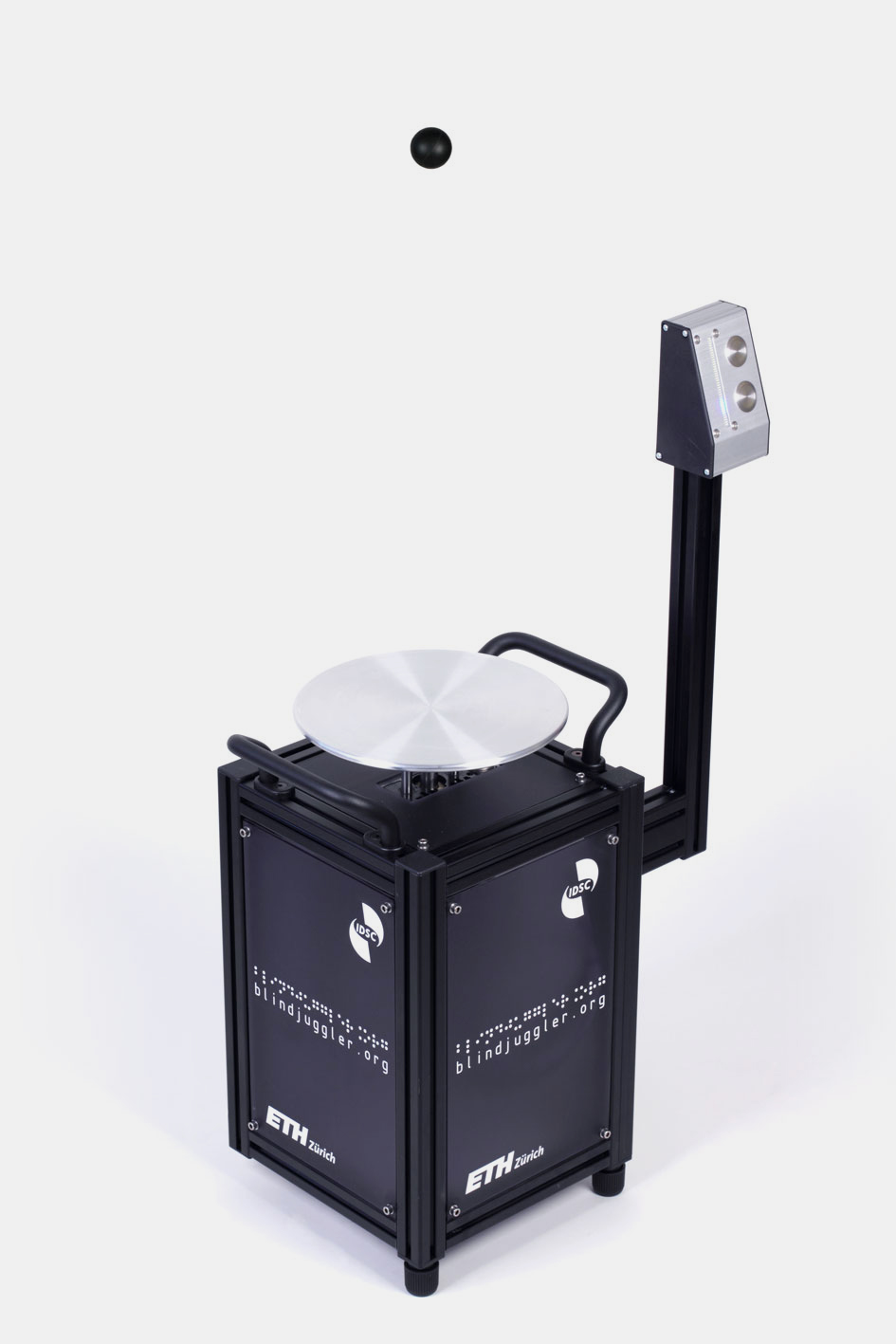
Hardware
The two main parts of the Blind Juggler are an aluminum paddle and a linear motor that actuates the paddle. Below we present an overview of the mechanical parts of the robot, as well as some details about the electronics. Finally, we show some measured results obtained with the first prototype.
MOTOR
We generate the motion of the paddle with a linear motor from LinMot. The motor is powerful enough to juggle a wide range of balls at a height of at least 1.2 meters. Note that the linear motor is the only actuator of the robot – the robot is not able to tilt or pan the paddle, for example.
The motor (datasheet) is further equipped with a linear guide that compensates for forces and moments that are not acting in the motor’s actuated direction. The magnetic spring cancels out gravitational force acting on the moving parts, which lowers the motor power requirements (datasheet).
PADDLE
The parabolic paddle was CNC-milled following this drawing. It is 0.3m in diameter and weighs about 1.34kg. The total mass actuated by the motor is about 3.6kg.
BALL
The Blind Juggler is able to juggle a wide range of balls from table tennis balls to bouncy balls. Most balls, however, are not perfectly round or have seams that cause the balls to bounce off the paddle when juggling at heights above 0.5 meters (~2 feet). Only solid precision balls made from Nylon (PA-6.6) enable the robot to juggle at its highest apex heights. In experiments, we use precision balls from ball valves with a diameter of 12 millimeters (~0.5 inches). These balls are manufactured to a high precision in roundness and diameter. You may find a video that compares different balls on the video page.
Trajectory Control
We use a controller (datasheet) with integrated power electronics from LinMot. The controller takes care of the low-level trajectory control and is able to drive the quadratic profiles we set over a serial (RS232) communication. We trigger the start of the motion by toggling a digital input of the motor controller, which allows precise timing of the motion. Lastly, the controller provides position information in the form of digital encoder signals with a resolution of up to 1 micro meter.
The high-level controller was prototyped with a D-Space (DS1104) real-time system. A program coded in C takes care of all the feed-forward control of the robot. The D-Space system’s digital outputs are used to trigger the motion controller. The portable version of the Blind Juggler is equipped with a STM32 microcontroller to take care of the high-level control. On the right, you find a picture of the electronics of the portable version of the Blind Juggler.
A Sample Trajectory
Based on the apex height, we determine the period time of the motion, i.e. the time between two impacts of the ball. The apex height, together with the coefficient of restitution of the ball, further define the nominal speed of the paddle at impact. The coefficient of restitution is a number that describes how bouncy the ball is, or, in other words, how much energy is lost at impact. The number represents the ratio of the outgoing ball speed to the incoming ball speed. A perfectly elastic ball has a coefficient of restitution of one, the outgoing ball speed is the same as the incoming ball speed, and no energy is lost. A perfectly inelastic ball has a coefficient of restitution of zero, and the outgoing ball velocity is zero, no matter how fast the ball was before the impact. Think of dropping a bouncy ball to the floor versus a beanbag: the coefficient of restitution of the bouncy ball is close to one, while the coefficient of restitution of the beanbag is close to zero. On the stability page, we further explain the stabilizing paddle acceleration at impact, which must be negative.
In the figure to the right, we show a model trajectory designed for a juggling height of 1.2m and a coefficient of restitution of 0.9 (about as bouncy as a Superball). The different parts of the trajectory are marked with the red and green lines. The green lines mark the nominal hit time, while the red lines mark the different trajectory sections, i.e. acceleration to maximal speed (a), deceleration during expected hit time (b), retraction (c) and idling (d).
Deceleration Duration: A Free Parameter
There is one more parameter of the trajectory we have not yet determined: the duration the robot should decelerate the paddle. The ball does not always bounce up to the same height – it randomly reaches an apex that is a bit higher or lower each time. There are many reasons for this, including imperfections of the ball itself, and varying bounciness of the paddle depending on impact location.
We determine the time the paddle is decelerating based on measurements of impact times. In the trajectory graph to the right, this duration is depicted as the interval between the first two red vertical lines (part b). During this time, the paddle decelerates with the desired deceleration of about -5 meters per squared seconds, which corresponds to about half the earth’s gravitational acceleration.
Measurements
The measurement data was recorded as shown in the video below: A microphone is used to measure the impact times. As an impact is detected, the red LED-array to the right flashes up and we extract the ball position from the video frame.
RESULTS
For more detailed experimental results, please refer to the papers available on the publication page. The following figures illustrate some of the recorded data. In the picture on the right, a video frame is overlaid with the extracted impact locations from a longer run of the robot. The standard deviation of the impact location is 16.3 millimeters. Therefore, 70% of all impacts occur within 16.3 millimeters from the paddle center.
The figure on the right shows the graph for the apex height distribution for a nominal height of 1.05 meters. The standard deviations of the fitted Gaussian distribution is quite small, 5.5 millimeters, which means that 70% of all measured apex heights are closer than 5.5 millimeters from the ideal height. The decelerating motion of the paddle alone results in a very steady apex height of the bouncing ball – without any feedback.
VIDEOS
Video that explains the basics of the Blind Juggler.
The measurement data was recorded as shown in this video: A microphone is used to measure the impact times. As an impact is detected, the red LED-array to the right flashes up and we extract the ball position from the video frame.
Demonstration of juggling robustness of the Blind Juggler. Vertical as well as horizontal stability is demonstrated.
Close up of the ball apex when the Blind Juggler is juggling at 1.05 meters . Open-loop vs. closed-loop (H2-optimal control) performance is compared (more info in publication).
The Blind Juggler demonstrates high apex juggling (2.0 meters, almost 7 feet).
In order to find the best ball to juggle, we conducted extended experiments to evaluate the juggleability of different objects.
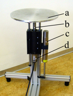
The first prototype of the Blind Juggler
a: aluminum paddle, b: linear motor slider, c: magnetic constant force spring, d: linear motor stator.
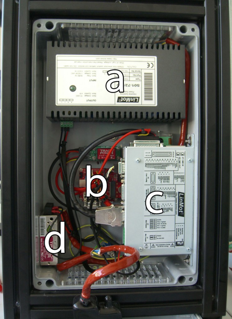
Electronics of current Blind Juggler
a: Motor Power Supply (72V DC), b: STM32 Microcontroller, c: Servo Controller, d: Logic Power Supply (24V DC).
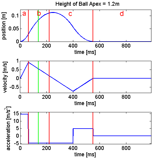
Paddle
The position, velocity, and acceleration trajectory of the paddle.
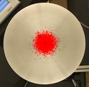
Impact location data, juggling height 1.05m, 5789 impacts.
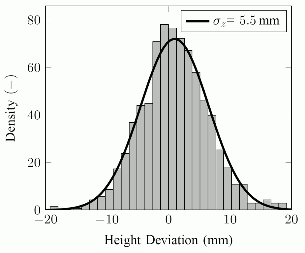
Histogram and fitted Gaussian Distribution to apex height deviation data. Juggling height 1.05m, 1079 measurements.
